Condition:
- The Camera has to be connected and adjusted in advance.
- Ensure data transfer between PC workstation and LCS works proper (Test data transfer with tool ‘amcap.exe’ in subfolder ‘Tools’ of the program folder at your individual eurolaser customer CD).
- This procedure requires 3 – 6 pcs. of white card board / paper 140 up to 200g/sheet.

Caution:
Laser in action! This procedure requires trained personnel for operating the Laser Cutting System (LCS). This short instruction assumes basic user knowledge about the eurolaser LCS (G3/S3 systems) and its user software LaserScout POSITION (or OS Production resp. OS Production & Design).
Fast moving axis possible! Keep safety distance and watch your hands!
Instruction:
Follow the instructions given in order to the numbers:

1. Start the system in normal operational mode.
2. Initialize the Z-axis onto the material support. After OK, lift the nozzle approx. +2 mm up.ESC 1-1-1-2-1 OK
3. Place the sheet (A4 print of test pattern) "Camera Offset_GBR.pdf" (subfolder: "Test jobs\Camera-Offset") at any position of the table (e.g. close to the 0/0-Position of the system)
4. Define a reference position at the lower right corner of the paper: ESC-[F8]-3. Switch vacuum ON and fix the sheet of paper additional with some tape at two points. It should not move at all!

5. Switch the system to ‘ONLINE’.
6. Start user software and open file ‘Camera Offset_GER.job’ (\Test jobs\Camera-Offset of the OS-Program folder).

7. Choose for the layer ‘Cutting contours’ (green) those parameter setup defined for ‘200 g. Paper Cut’. Define the layer ‘Information’ invisible by clicking the eye (crossed). Registermarks (Reg.-Marks) are displayed in red.

8. Click Register: ‘Settings / Standard Settings / Register Jog Marks’, and set as type Video Marks.Set the size = 6 mm.

9. Open the output device window.
10. Set Number of copies = 1 and Production mode = manually. Click on ‘preview’

11. Edit ‘Mark settings’ and define the Reg.-Marks for the test pattern:
Mark settings / Mark recognition / Normal / OK
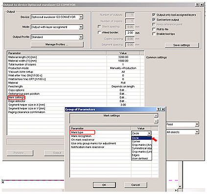
Mark settings / Mark type / Circle / OK

12. The preview window pops up and shows the camera live-view. Click-right for open the sub-windows and click ‘Default settings/ Mark Recognition’.

13. Move the Camera by using the cursor keys at your PC-keyboard to the first Reg.-Mark closest to the REF point
- A red circle at the video screen indicates, the Reg.-Mark is inside the search radius of the camera.
- A green circle at the video screen indicates, the REG-Mark is already identified. If it does not automatically switch to green click on ‘Move to Mark’ until it turns to a green circle.
- If the circle still remains red marked, click on the ‘Measure’ button. Now the Reg.-Mark has been scanned and the ‘Mark size’ value displayed will be adapted. At the spell State the values in Pixel are shown e.g. D(act) 54,8 PixRes.
- Save those values with a click on the ‘Save’ button.The window will close now.

14. At the preview window (camera live-view): Click-right for open the sub-windows and click ‘Default settings / Set Camera Offset’.

15. Move the axis with the camera by your PC-cursor keys down to the bigger black test circle on the paper and stop approx. in the centre. Click on ‘Cut mark’ The laser will cut a circle into the paper now.
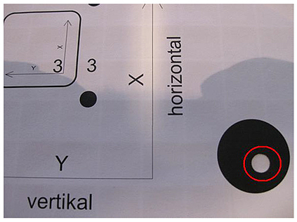
16. Put a white sheet of paper underneath the test cut circle to increase the contrast.
Caution: The test-pattern paper should not move anyway on the table!

17. Touch any cursor key at the PC shortly. The camera returns now back to the test cut circle. If required control the camera by pressing the cursor keys to a closer area so the identification is confirmed by the green circle. Click on ‘Measure’.
- The camera software measures now automatically the difference in X- and Y-axis direction. This defines the new OFFSET values in the window ‘Camera Offset’.
- If the measurement is constant about 5 seconds, the measurement procedure is completed.
18. Click ‘Save’ under ‘Camera Offset’ to complete the procedure.
19. The Offset assignment is verifiable by activating the Test-Pattern (print on the Paper). Switch the system to ‘ONLINE’.
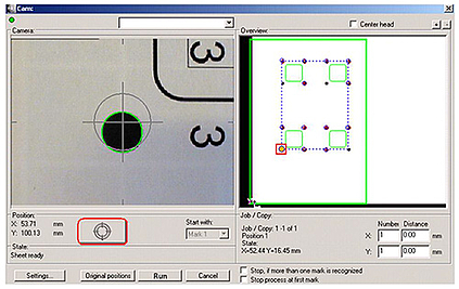
20. Move the axis with the camera (red square in the right window) by your PC-cursor keys down to the closest Reg.-Mark next to the temporary Ref.-Position until the identification is confirmed by the green circle.
- Click on the recognition mark symbol to start the recognition sequence for all Reg.-Marks.
- Those Reg.-Marks signed green are identified by the camera.
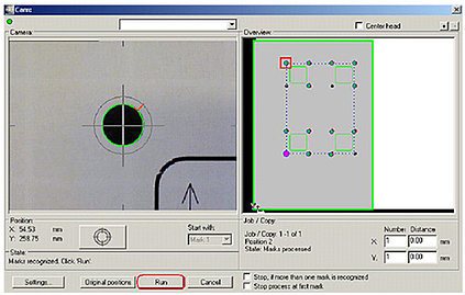
21. All identified Reg.-Marks (min. 2 pcs. per each contour, better 3 pcs.) are now signed green andchecked with a checkmark.
Click on ‘Run’ to accept the Reg.-Marks and start the contours cut out.
If too many Reg.-Marks are not clearly identified, check the following issues:
- shows the area illumination enough brightness and light is diffuse?
- how is the contrast of the test-pattern (quality of print)?
- check the fixing of the paper / card-board. Is the paper / card-board positioned nearly parallel to the axis?
- repeat procedure from no. 17.
22. The preview-window opens. Check the position on the screen and compare with the paper positioned at the table. Note: X-axis on the screen is horizontal!
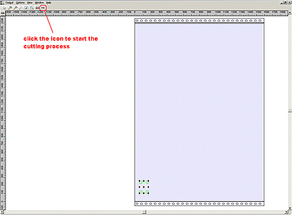
23. Click on the output icon to start the cutting sequence.
24. After cutting is completed, switch system to ‘OFFLINE’ mode and move the bar (Y-axis) in a rear position (approx. +500 mm), so you can evaluate the results.

25. If the new offset values are correct, the contour-cuts are centered according the printed frames. Each contour shall show the same thickness of frames to each direction.

26. If the contours are not centered (not placed exactly in the middle position the offset values may need some corrections. Click-right on the preview-screen and open the popup window. Click ‘Default setting’ / ‘Set Camera offset’ and make the necessary corrections under ‘Camera Offset’ X-Y according the X-and Y-arrows on the Test-Pattern print.
- Typically the correction may need some 1/10 [mm] only. Mind the algebraic sign!
- Click ‘Save’ to confirm the input.
- Place a new Test-Pattern print on the table – same position.
- Repeat the procedure from no.16. until the result is good enough for the next laser application.
Note: In case of lost position proceed as follows:
- Stop and close the Plot-Manager (icon right/lower PC monitor frame)
- Clear the REF-Point at the system´s user panel [F8] - 2 and define a new REF-Point [F8] - 3 move manually to the position, than confirm message. Click ‘OK’.
- Clear the system buffer memory, ‘ECS 2-4-1’ / ‘OK’
Note: Check the Reg.-Mark identification frequently before starting any high quality jobs. Especially after module- or lens-system exchange the test procedure for “Checking the camera offset” should be performed.
Do you have any questions? We are pleased to advise you.
